25+ pid controller block diagram simulink
Digital PID controller can also be represented in this form leading to particular choices of R S and T Landau 1998. The block diagram of a simple PID controller is provided in the figure below Figure 2.

Solving Linear Equations With Simulink Tutorial 4 Solving Linear Equations Linear Equations Equations
Block diagram of control mode.
. In Simulink a PID controller can be designed using two different methods. For instance consider a continuous-time SISO dynamic system represented by the transfer function syss NsDs where s jw and Ns and Ds are called the numerator and denominator polynomials respectively. Identifying the COMx number from the USB VIDPID is preferable for end consumers as the USB VID.
The distinguishing feature of the PID controller is the ability to use the three control terms of proportional integral and derivative influence on the controller output to apply accurate and optimal control. Peak Current Mode System Block Diagram. It reads and writes to many open file formats such.
We would like to show you a description here but the site wont allow us. The simulation results using the AWPSO algorithm are better than the simulation results where the PID controller has been tuned with the Zeigler and Nichols approach Aboelela et al 2015b. Single-Loop System Block Diagram.
Lets now move towards a simple example regarding the working of a simple PID controller using Simulink. The PLCnext AXC F 2152 controller for the Axioline IO system is fast robust and easy to use. A generalized state-space model genss object when the numerator or denominator input arguments includes tunable parameters such as realp parameters or generalized matrices genmat.
Ladder diagram LD Function block diagram FBD Structured text ST C. Transfer functions are a frequency-domain representation of linear time-invariant systems. Design a 2-DOF PID controller with a target bandwidth of 075 rads for a system represented by the following matrices.
173 sday 20 ppm at 25 C. If you specify other types of graphics objects such as an axes then saveas saves the parent figure to the object. The Motor Control Library is a collection of functions that you can use as building blocks for implementing Field Oriented Control FOC of 3-phase motor control applications on dsPIC Digital Signal Controllers DSCs.
Parametric modeling allows you to easily modify your design by going back into your model history and changing its parameters. The RST canonical structure of a digital controller. In the case of AWPSO the settling time for IAE ISE and ITAE performance indices is less than 15 s.
How to install cemu ubuntu FreeCAD is an open-source parametric 3D modeler made primarily to design real-life objects of any size. While the controlled systems are predominantly analog systems ie. The library functions are designed to be used within any application framework to create high-performance memory-efficient and flexible motor control.
In C implementation to avoid unnecessary conversion I think to get the tilt of accelerometer it will be better to just stick with ADCRx 512 using 10 bit adc to get the angle at 33V input at the accelerometer the typical 0deg position will be 165 which will yield also 512 in a 33V vref a greater than 512 value means tilt angle at the 1st quadrant then a less than 512. Create a state-space model with a sample time of 025 seconds and the following state-space matrices. Mac and Linux highly customizable and extensible software.
The block diagram on the right shows the principles of how these terms are generated and applied. The tf model object can represent SISO or MIMO transfer functions. Allowing for a continuous short circuit to be sustained when the ambient conditions are near 25 Celsius.
PID controller design using Simulink MATLAB. They could be described by the continuous-time mathematical equations todays controllers are predominantly digital systems so the block diagram of such a closed-loop control system can be represented rather by Figure 2Two new components are the DA and AD converters. A parallel-form PID controller pid model object when all the gains have numeric valuesWhen the gains are numeric arrays C is an array of pid controller objects.
The operation of the fast power reserve controller begins once the frequency deviation exceeds a certain threshold. 741 Using PID Controller. Saveas gcfMyFigurepng To save a Simulink block diagram use get_param to.
A 0 1-5-2 B 0 3. A control signal is sent from the detecting and triggering scheme to bypass the maximum power point tracking and enables power shaping as shown in Fig. Block diagram interconnections of dynamic systems.
Figure to save specified as a figure object or a Simulink block diagram. Block diagram of fast power reserve controller. Series connection of two models.
PID values are known for the USB to serial adapter device.

Pid Controller Design Using Simulink Matlab Tutorial 3 Muhendislik Elektronik Teknoloji

Block Diagram In Simulink Block Diagram Diagram Class Diagram

Pid Controller Design Using Simulink Matlab Tutorial 3 Controller Design Pid Controller Transfer Function

Build Your Own Microcontroller Based Pid Control Line Follower Robot Lfr Second Part Ermicroblog Microcontrollers Control Computer Technology

Permanent Magnet Synchronous Machine Matlab Simulink Permanent Magnet Magnets New Zealand English

Permanent Magnet Synchronous Machine Matlab Simulink Example Permanent Magnet Magnets New Zealand English
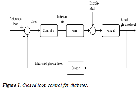
Closed Loop Blood Glucose Control In Diabetics

Pid Block And Manual Pid Matlab Answers Matlab Central Manual Blocks Answers

How To Use Lags And Delay In Simulink Tutorial 9 Controller Design Pid Controller Design

Control Tutorials For Matlab And Simulink Simulink Basics Tutorial Interaction With Matlab Interactive Control Tutorial

Pid Controller Design Using Simulink Matlab Tutorial 3 Controller Design Pid Controller Control

Pdf Pso Tuned Pid Controller For Controlling Camera Position In Uav Using 2 Axis Gimbal

Quadcopter System Diagram Pid Controller For The Quadcopter Pid Controller Quadcopter Control

Pid Controller Design Using Simulink Matlab Tutorial 3 Controller Design Pid Controller Control Engineering

Build Your Own Microcontroller Based Pid Control Line Follower Robot Lfr Second Part Ermicroblog Microcontrollers Control Computer Technology
2

Control Tutorials For Matlab And Simulink Motor Speed Pid Controller Design Controller Design Pid Controller Motor Speed